At this point, you should have the Sensors installed, the Areas and Groups defined, and access to your dashboard. If you skipped one of those steps, please, refer to the previous tutorials:
- Create Your Account
- Sensor Placement
- Preparation for Retail Stores or Events
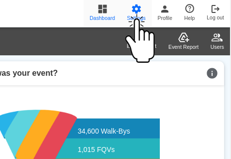
Step 1: Accessing Settings
- Log into the dashboard.
- On the top bar, click on Settings.
Step 2: Adding & Editing Areas
- On the setup screen, click on Areas.
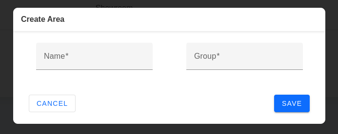
- To add an Area, click on (+) in the upper right corner. To edit an Area, click the edit icon next to the area name.

- Enter the name of the Area and the Group that Area will belong to.
- Click Save.
- Repeat steps 2-4 for each Area.
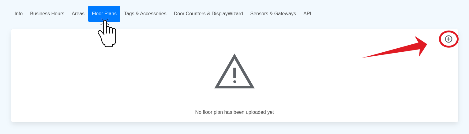
Step 3: Adding the Floor Plan
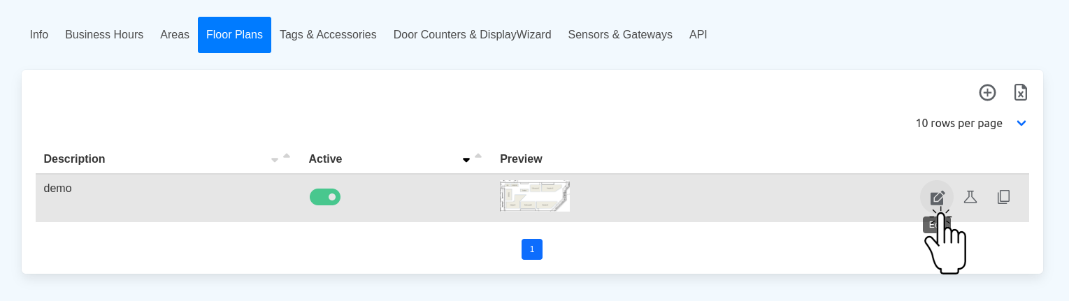
- On the setup screen, click on Floor Plans.
- To add a Floor Plan, click on (+) in the upper right corner.
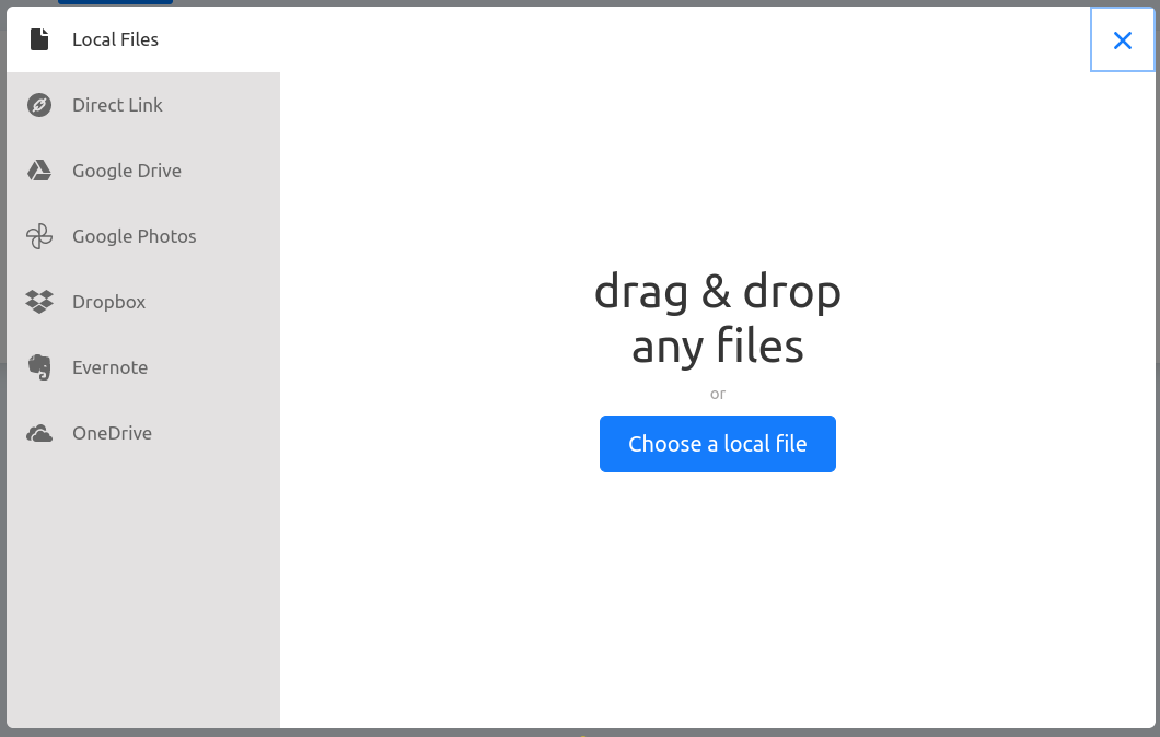
- Upload the drawing (PNG or JPEG format) from your favorite cloud or local disk.
- You can crop and rotate the drawing as needed. FastSensor recommends landscape format (horizontal rectangle).
- You can crop and rotate the drawing as needed. FastSensor recommends landscape format (horizontal rectangle).
- Click Add to confirm.

Step 4: Editing the Floor Plan
- On the setup screen, click on Floor Plans.
- Click the edit icon next to the Floor Plan drawing.
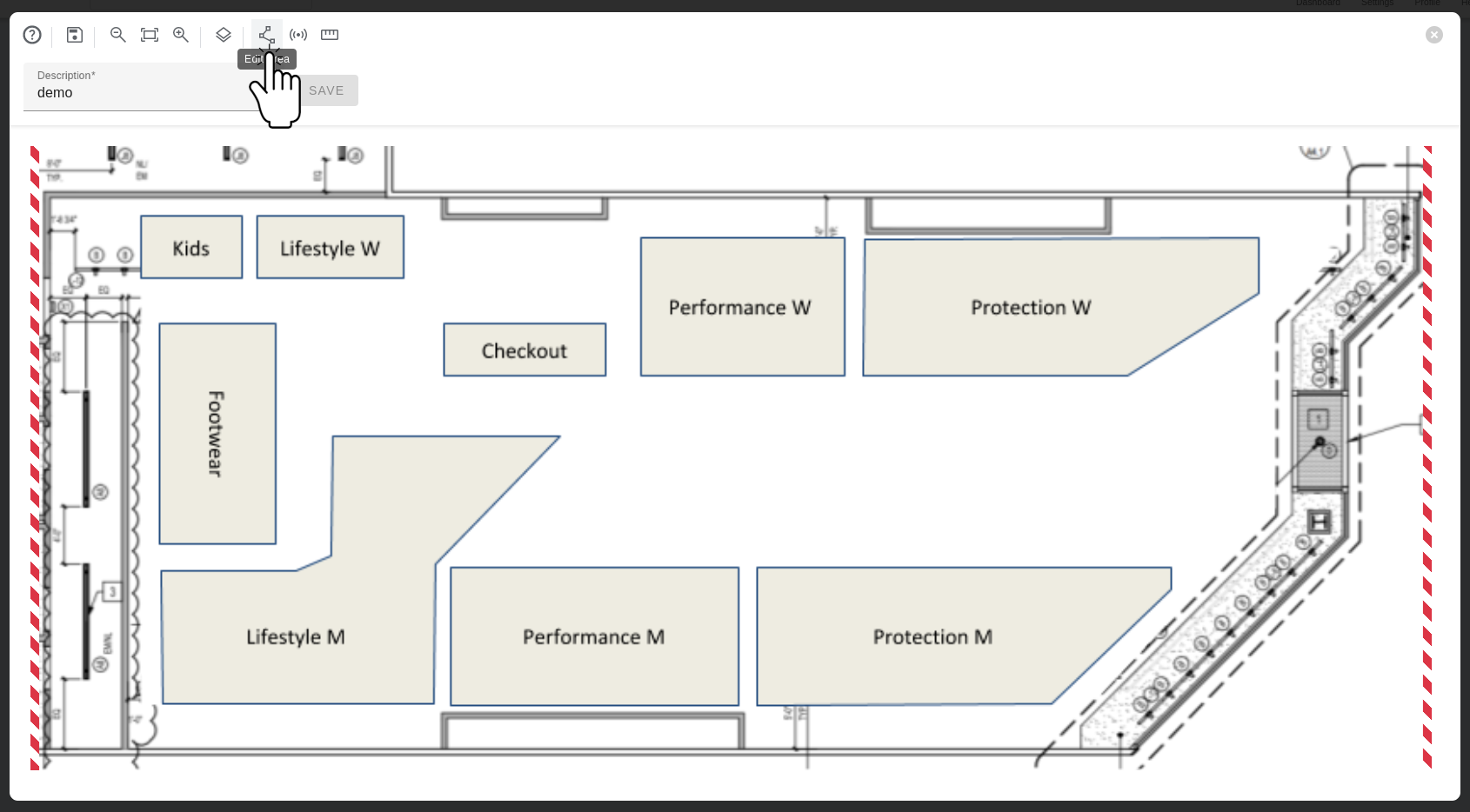
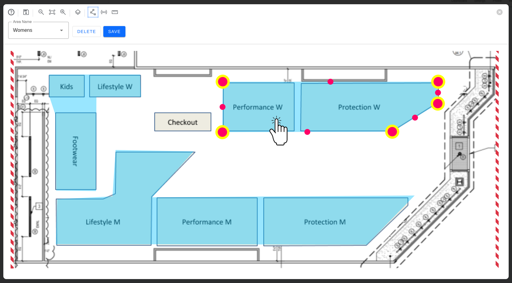
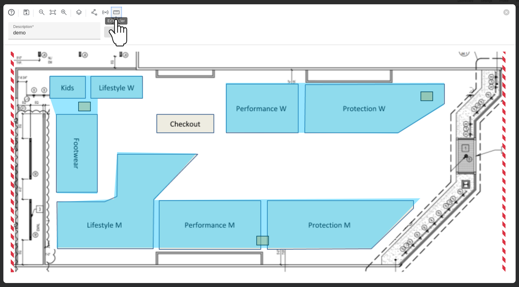
Step 5: Mapping Physical Areas on the Floor Plan
- Click the Edit Area icon on the top bar to draw Areas.
- Click any place on the drawing to add vertices to a polygon and define the Areas. Each time you click the drawing, you will add a new vertex to the polygon.
- Click and drag the vertex to move and adjust the position.
- Use the circle marker on the middle of the lines to curve the side and create a rounded shape.
- To remove a vertex, double click it.
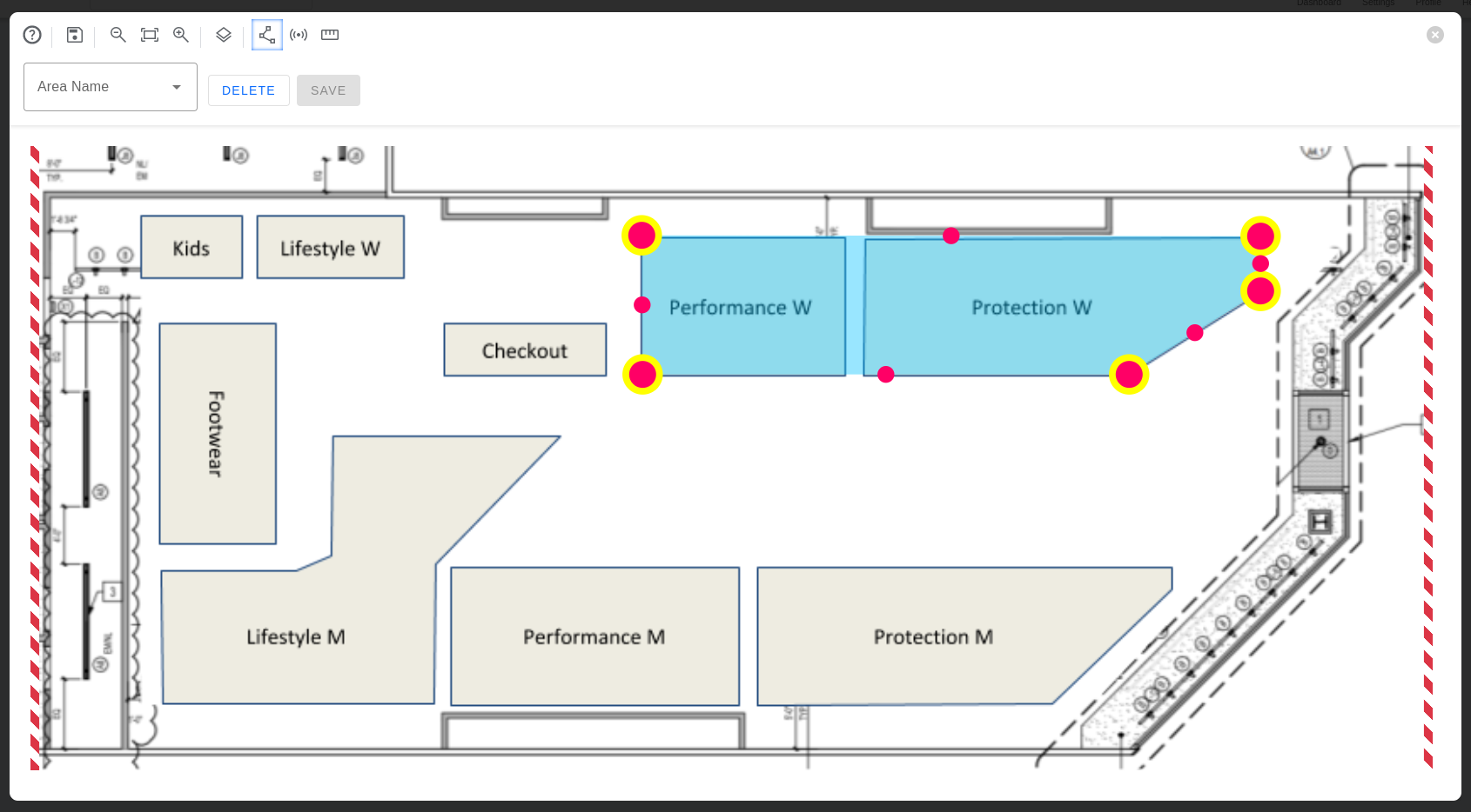
- When done, click on Area Name drop-down on the top bar to map the shape to a physical Area.
- Select the Area from the drop-down box to associate to the shape.
- Click Save.

- Repeat steps 2-8 to map all the Areas.

Editing Areas on the Floor Plan
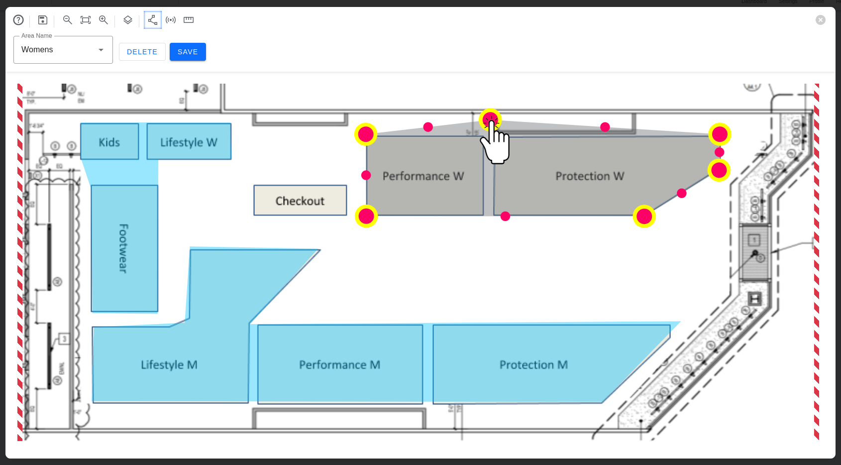
- Click the Edit Area icon on the top bar to start editing areas.
- Click the Area on the drawing to select it.
- Use the same controls you used to create the Area to edit it:
- Click and drag the vertex to move and adjust the position.
- Use the circle marker on the middle of the lines to curve the side and create a rounded shape.

- To add more vertices, double-click the Area to enter the vertex edit mode (the Area will turn gray).
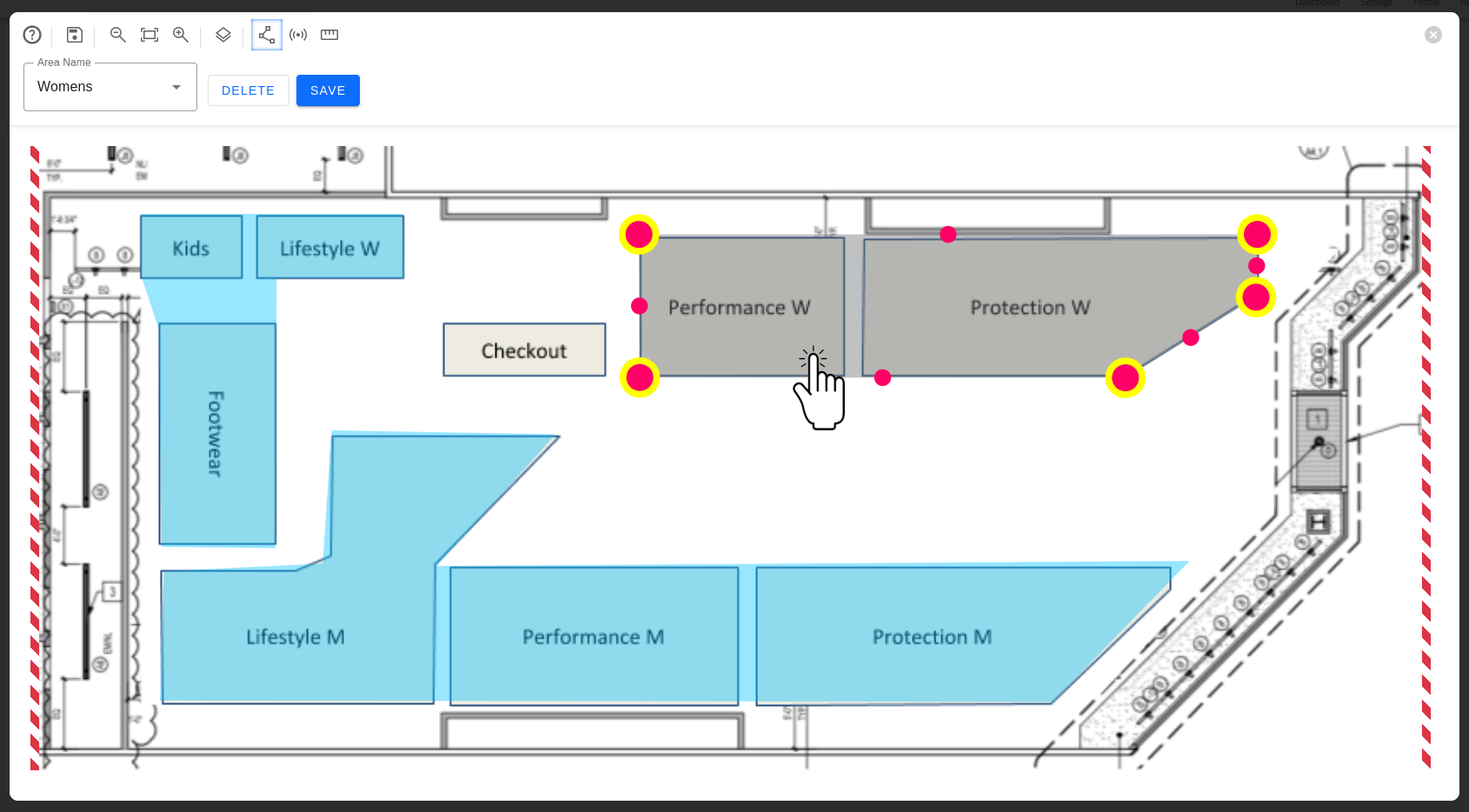
- Then, click any place to add vertices.
- When done, click Save on the top bar.
If you are adding a new Area or editing one, you must finish the process before editing another Area.
Removing Areas From the Floor Plan
- Click the Edit Area icon on the top bar to start editing areas.
- Click the Area on the drawing to select it.
- Click Delete.
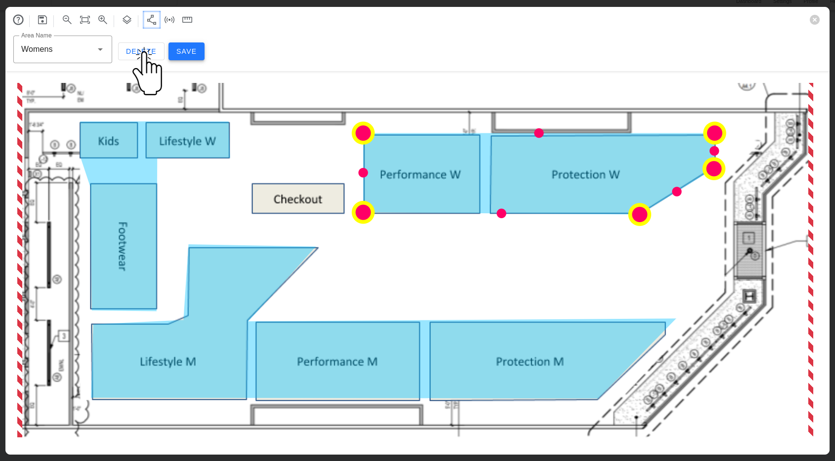
This will delete the Area shape from the floor plan, but not the Area from the Location. You can create a new shape and map it to an Area. This action cannot be undone.
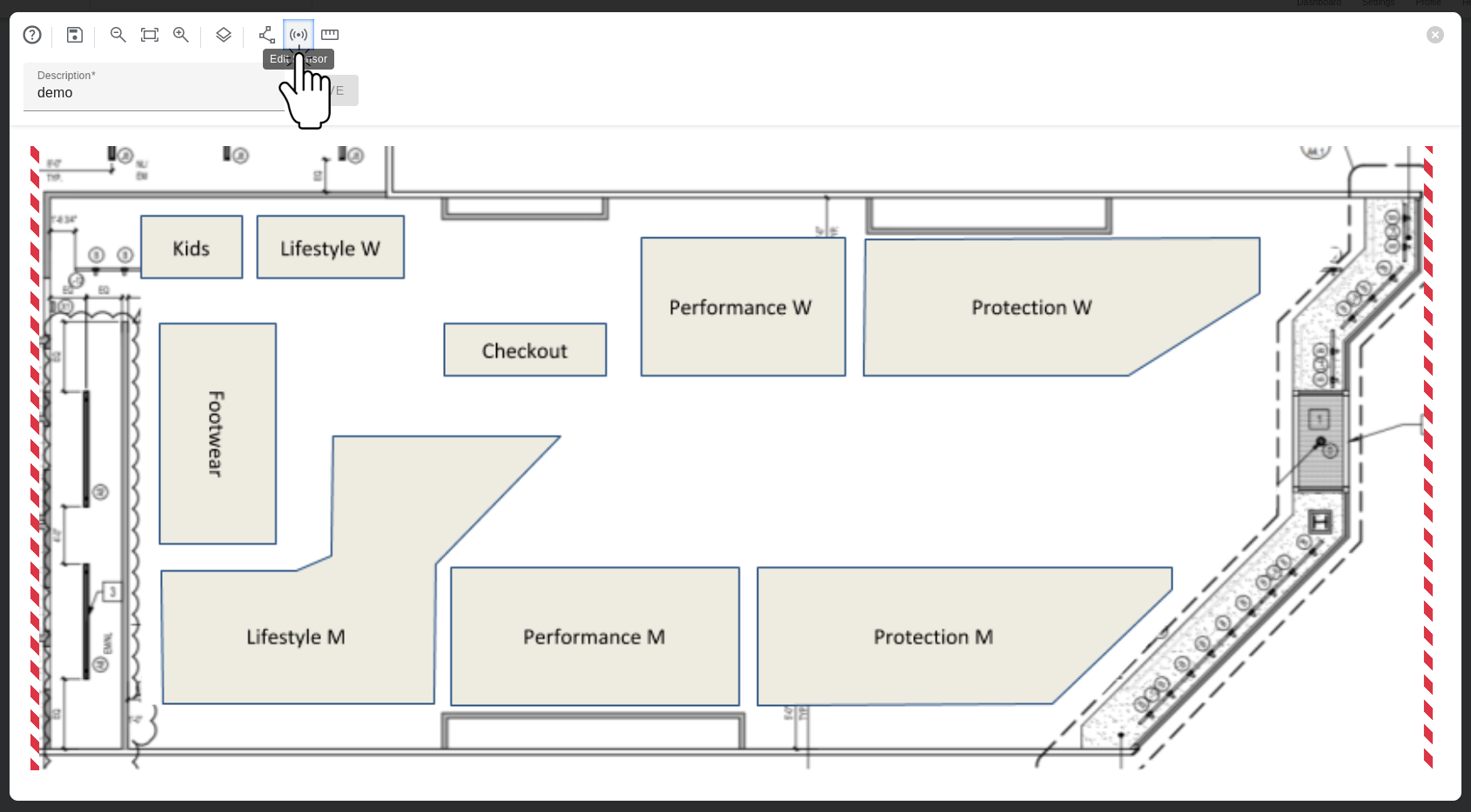
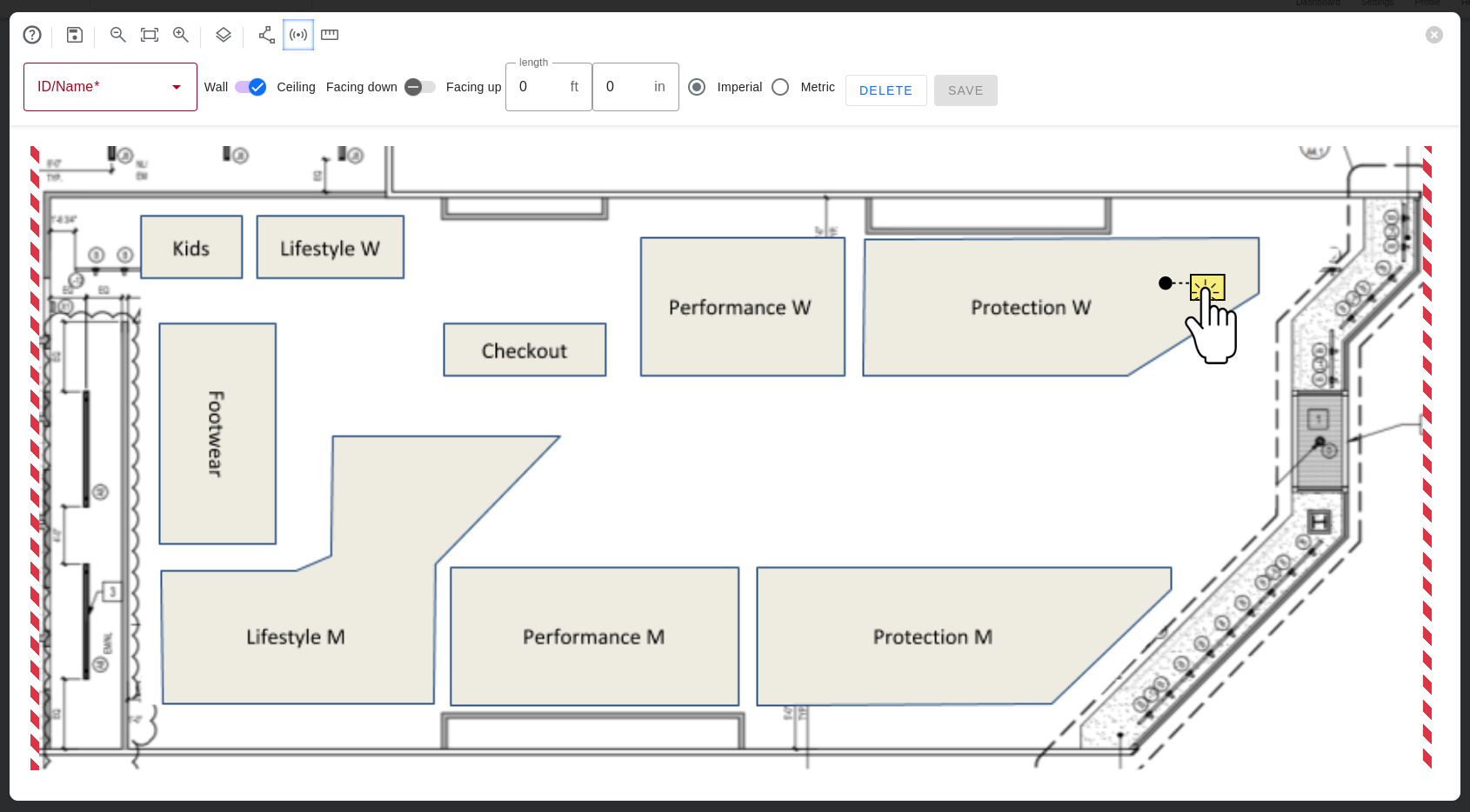
Step 6: Positioning the Sensors on the Floor Plan
- Click the Sensor icon on the top bar to activate Sensor Mode.
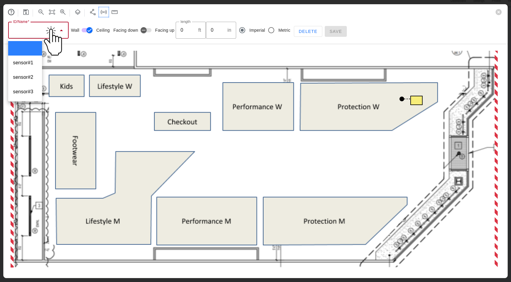
- Click the drawing to add a Sensor.
- Select the desired Sensor from the drop-down menu.
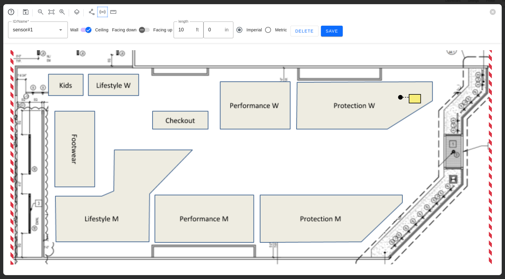
- Select the type of mount (Wall or Ceiling):
- For ceiling mount (horizontal), you can pick Upwards or Downwards according to the sensor orientation.
- For wall mount (vertical position), you can rotate the Sensor to indicate the direction it is pointing to.
- Enter the height of the Sensor. You can choose the unit system as needed: Imperial or Metric.
- Click Save.
Editing & Deleting Sensors
- Click the Sensor to select it.
- Drag-and-drop it to move the Sensor and change its position.
- To update the Sensor height, mount type, and other parameters, use the top bar and then click Save.
- To remove the Sensor, click Delete on the top bar.
Delete will remove the Sensor from the floor plan, but will not delete the Sensor connected to the Location. but not the Area from the Location. You can use Positioning Sensors to map it again. The delete action cannot be undone.
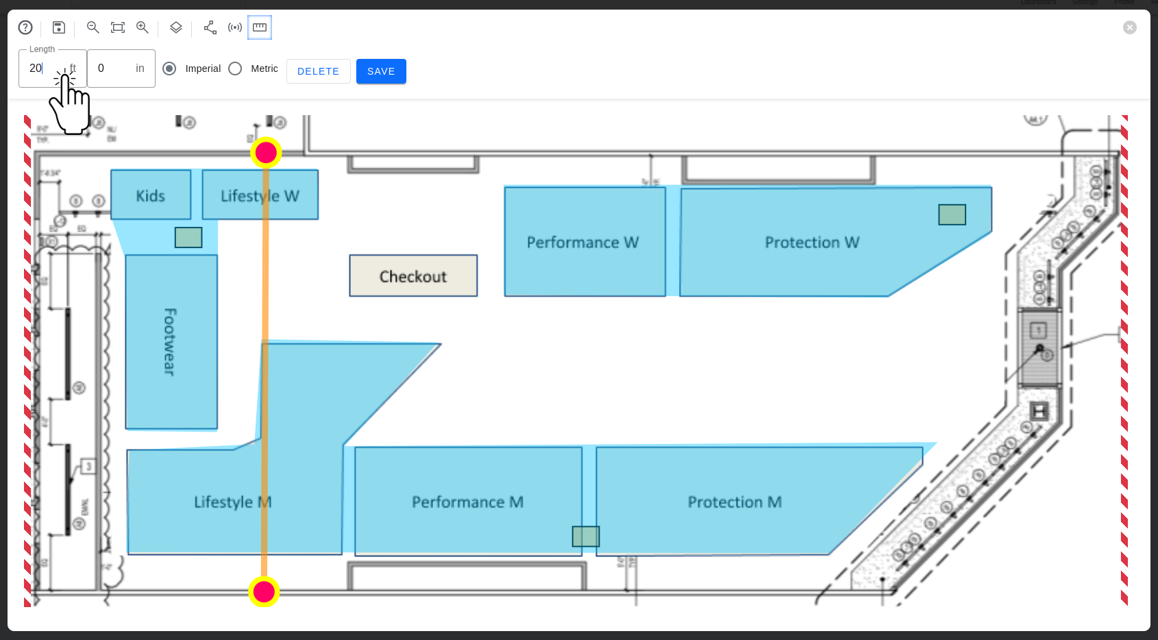
Step 7: Setting the Floor Plan Scale
Use a Ruler to define the Floor Plan drawing scale. Every Floor Plan must have one Ruler.
- Click the Ruler icon on the top bar to activate Ruler Mode.
- Click the drawing to add vertices and define the Ruler.
- Click and drag the vertex to move and adjust its position.
- To remove a vertex, double-click it.

- Enter the length of the ruler.
- When done, click Save.
Attention!
It is essential to place the Ruler correctly. Otherwise, it will impact the system's accuracy.
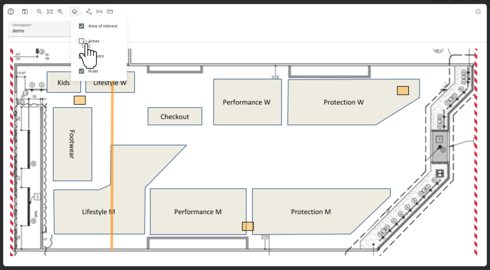
Step 8: Reviewing the Floor Plan, Areas, Sensors, and Ruler
The view of the Floor Plan with all the Areas marked, Sensors placed, and Ruler set.

Toggling Layers Visibility
- Click the Toggle icon to switch the visibility of the layers: Area of Interest, Areas, Sensors, and Ruler.
- Click on the check in front of the layer to hide it.